VMT FrameSense

3D container measurement for automated part stacking in the press shop
Home
/
Technologies
/
VMT FrameSense
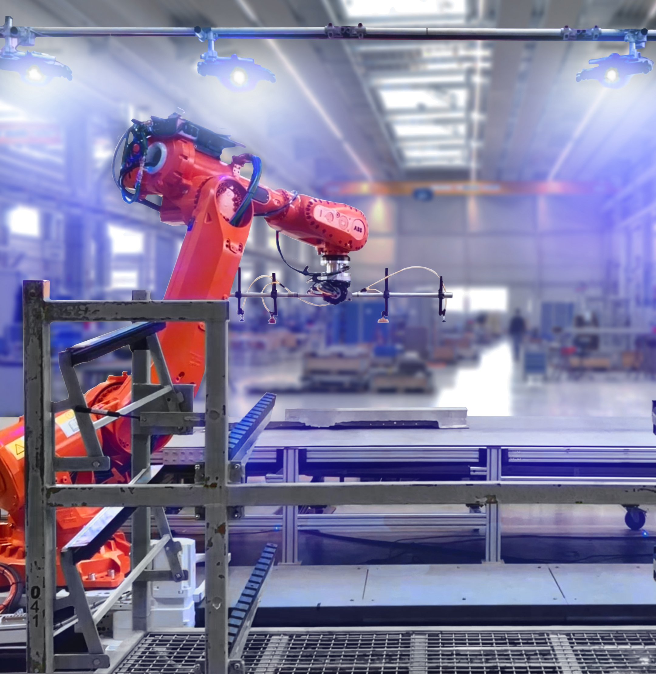
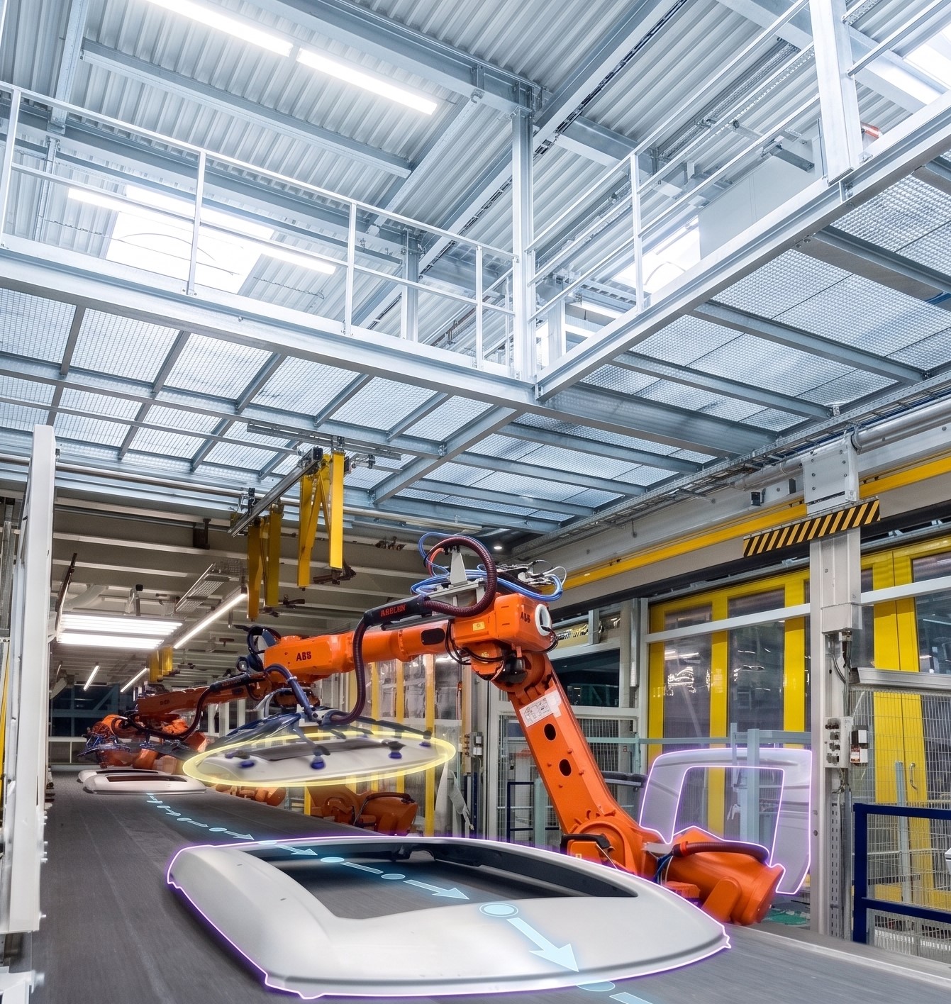
At the end of a press line, finished panels are stacked into containers for transport to the body shop. Those containers wear, deform and differ between suppliers, so frame parts or RPS points are not usable as references. FrameSense measures each container at its load-relevant structures instead: it determines the container position in space, takes local measurements inside the container, and inspects conditions such as latches, lever positions and profile clearance. Robots and PLCs receive calculated vectors and inspection results directly, so they never have to run measurement tasks themselves. The result is a stacking process that does not stop the line, and panels that do not get damaged by a robot hitting a closed latch, an interfering edge or a container that was never fit to be loaded.
Built for Worn Containers

Deformed or damaged containers are still loaded reliably. Position is measured without fixed references, X, Y and Z independently at the load-relevant points.

One System to Measure them All

Container position, local measurement and inspection combined in a single system, on one PC.

High Process Reliability

Static setup, no moving parts, independent of ambient light, with redundancy across sensors.
How it works

Point-Cloud Based Container Measurement
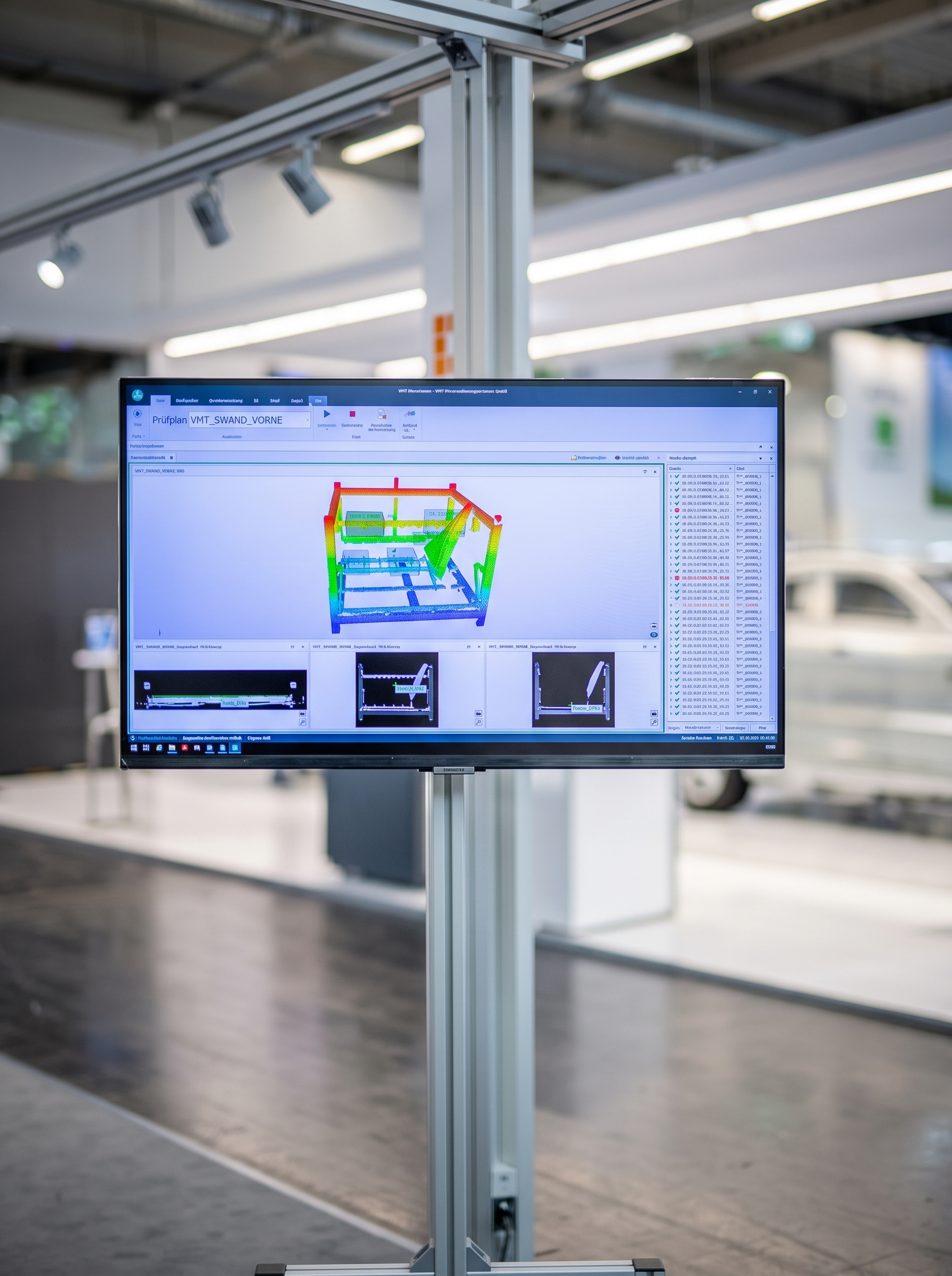
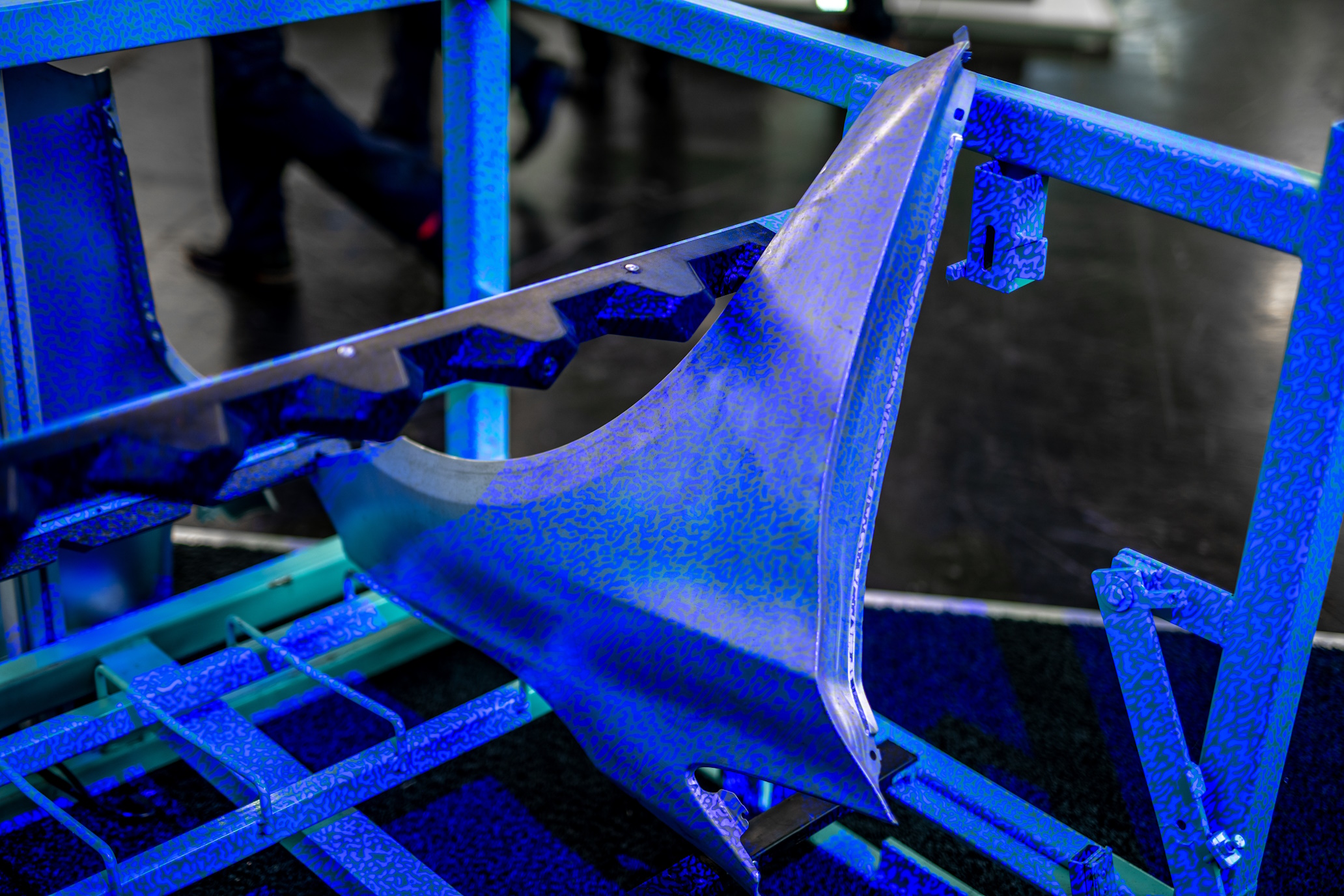
A form-based probing method captures the entire outer contour of the container instead of single features. Millions of 3D points are merged into one point cloud and compared against CAD data or a golden scan.
Measurement at Load-Relevant Structures
Toothed rails, tubes, plastic rails and cantilever arms are measured where they decide the storage position. X, Y and Z are determined independently per point, deviations outside those points are filtered out and do not distort the result.
Measurement Range and Cycle Time
Typical measuring field approx. 2.50 m wide × 1.80 m deep × 1.80 m high, expandable with additional sensors to around 4.50 m for larger cells. Measurement, evaluation and transmission run in parallel to the robot cycle.
01
How it works

Software & Control

VMT Software Platform
Freely configurable and continuously extended with new algorithms and evaluation methods. Container type and size are preselected by the PLC, which loads the matching inspection plan. One master PC can serve several cells along a line.
Inspection and Dimension Tracking
Latches, two-position levers, locking bars and profile clearance are checked in the same inspection plan, together with empty/full container detection. Local deviations of the container are measured and documented, tolerances are set outside the inspection plan.
Direct Data Supply to Robots and PLCs
Position vectors and inspection results are transferred in a defined sequence via Profinet. The robot only executes the corrected path.
02
Software & Control

Hardware & Integration

High-Precision 3D Sensors
Sensors with integrated measuring-field illumination. No external lighting, and results stay stable regardless of brightness, colour and ambient light. Up to 20 sensors per system.
Static Cell Layout
Sensors look crosswise into the container and are arranged for each cell layout individually. Nothing moves during measurement, which keeps results repeatable and robust.
IPC and Calibration
A dedicated industrial PC handles data fusion and evaluation, with screen visualisation and operating controls. Calibration runs via robot-guided sphere or plate, so recalibration after a sensor replacement can be done by plant personnel.
03
Hardware & Integration

Our team will be in touch as soon as possible.

FAST RESPONSE TIMES
EXPERT CONSULTING & SUPPORT
SOLUTION-DRIVEN APPROACH
01
02
03
04
Submit
Thank you! Your submission has been received!
Oops! Something went wrong while submitting the form.