VMT Plug & Pad Detection is an image processing system that inspects sealing elements on the vehicle underbody in the paint shop. It checks plugs and adhesive pads for presence, position, and type—performing a 100% inspection at the production cycle speed and linking the data to the vehicle body's identification number. The system replaces manual visual inspection and ensures that no missing or incorrectly placed sealing element leaves the paint line undetected. The application inspects the vehicle underbody either inline as it moves along the conveyor system or at a stationary station.
Underbody
All fastening points on the vehicle underbody in a single inspection process
Comprehensive
Every vehicle body during the production cycle, rather than random sampling.
Manufacturer-independent
A detection approach for various vehicle bodies and OEMs
How it works
Recipe and inspection plan
Before each cycle, the system controller transmits the vehicle type, option bits, and identification number. VMT Plug Detection then activates the corresponding inspection plan. Unoccupied holes are deselected via the option bits and yield a "pass" result without inspection. There is exactly one inspection plan for each vehicle type; a change in type takes effect before the next measurement. Inspection points are derived in advance from the vehicle body's CAD data and defined as search areas within the inspection plan. This significantly reduces the effort required to commission new vehicle types.
Underbody detection
At each inspection position, a 2D camera captures an image of the underbody. A deep learning model detects and classifies the elements within the image into the categories "pad," "plug," and "hole." The "hole" category corresponds to a visible opening without a sealing element and immediately results in a "not OK" (NOK) decision. Each element is inspected for presence, position relative to a fixed reference feature, and type. The position check serves solely to verify placement; no metric measurements or calibrations are performed, as the system derives size and type from the AI classification and the bounding box.
Result and documentation
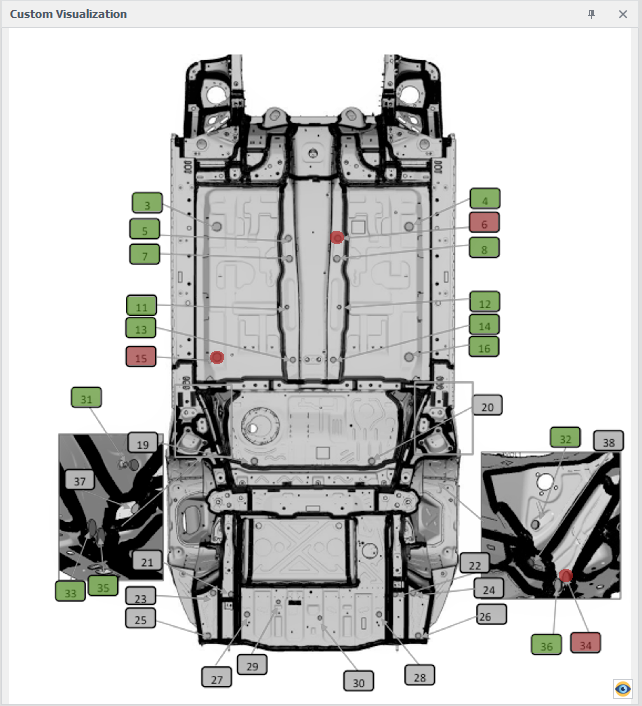
The system provides a fail-safe OK/NOK decision to the PLC: a missing element is always classified as NOK and never defaults to an "OK" result. Additionally, status signals are available for "measurement in progress," "system ready," and "watchdog active." Results are displayed using an underbody schematic known as a "butterfly diagram." Each inspection point appears green for "OK," red for "missing" or "incorrect," and gray for "not included in the recipe." Every result can be retrieved via the identification number. The archive stores reports for long-term retention, not raw images.
01
How it works
Software & Usability
Operation
The user interface features a "butterfly diagram" of the underbody displayed on a large monitor, supplemented by plain-text error messages and an overlay showing actual versus target positions. The display supports panning and zooming. Designed for operators with no prior knowledge of image processing. Available in German and English.
User Management and Documentation
Role-based access levels separate viewing, operation, and parameterization. Every intervention and parameter change is logged with a timestamp and user ID. A statistics view displays OK/NOK figures and the NOK rate per inspection point over selectable time periods, including CSV export for quality analysis.
Configuration and parameterization
The operator works in "operator mode": shifting inspection zones and pre-positioning points, adjusting detection thresholds, and selecting or deselecting inspection scopes. Inspection plans can be exported and imported at other locations; only camera-specific parameters are adjusted there, while inspection point coordinates remain unchanged. Retraining the AI models is a task reserved exclusively for VMT and is deliberately inaccessible via the user interface. This ensures reproducible detection performance throughout the system's service life. The software platform is VMT MSS.
02
Software & Usability
Hardware
Camera and lighting
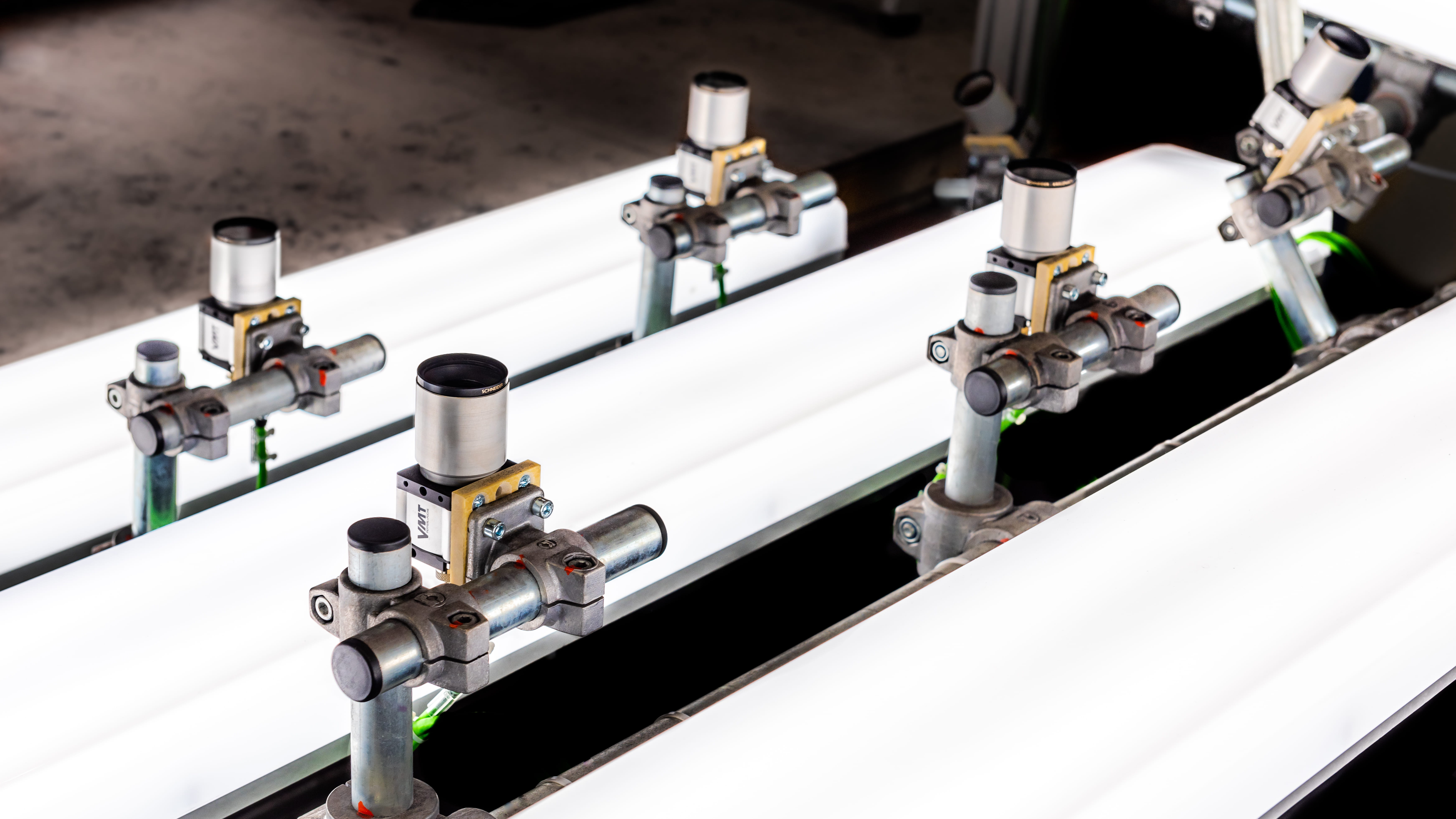
2D industrial cameras with PoE, each with a dedicated, individually controllable LED area light. Monochrome is the standard; color cameras are used where adhesive pads are being inspected, as aluminum and plastic pads are virtually indistinguishable in monochrome. The number and positioning of the cameras depend on the vehicle body type and the scope of inspection, and are determined on a project-specific basis.
In-line or stationary inspection
Both versions utilize the same system platform and AI models, differing only in their hardware configuration. In the in-line inspection setup, the cameras are fixed to the conveyor system, and image capture is triggered by the system controller. With the stationary version, image capture takes place at a defined stop position, enabling additional inspection points and perspectives. The system is configured on a project-specific basis, taking into account the body type, inspection scope, and available space on the production line.
System platform and peripherals
Industrial IPC with VMT MSS housed in a standards-compliant control cabinet, accessible from outside the inspection cell, and featuring remote access for VMT service. Connection via native PROFINET, not a gateway. All components in the application area are rated at least IP54. Backup and restore functions are available via the user interface or as scheduled tasks. A bypass mode renders the system completely inactive, signals this status to the PLC, and allows the conveyor system to continue running without inspection.
03
Hardware
Our team will be in touch as soon as possible.
FAST RESPONSE TIMES
EXPERT CONSULTING & SUPPORT
SOLUTION-DRIVEN APPROACH
Thank you! Your submission has been received!
Oops! Something went wrong while submitting the form.