
VMT Fiber Geometry Check

Automated geometric measurement of hollow-fiber membranes
Home
/
Technologies
/
VMT Fiber Geometry Check
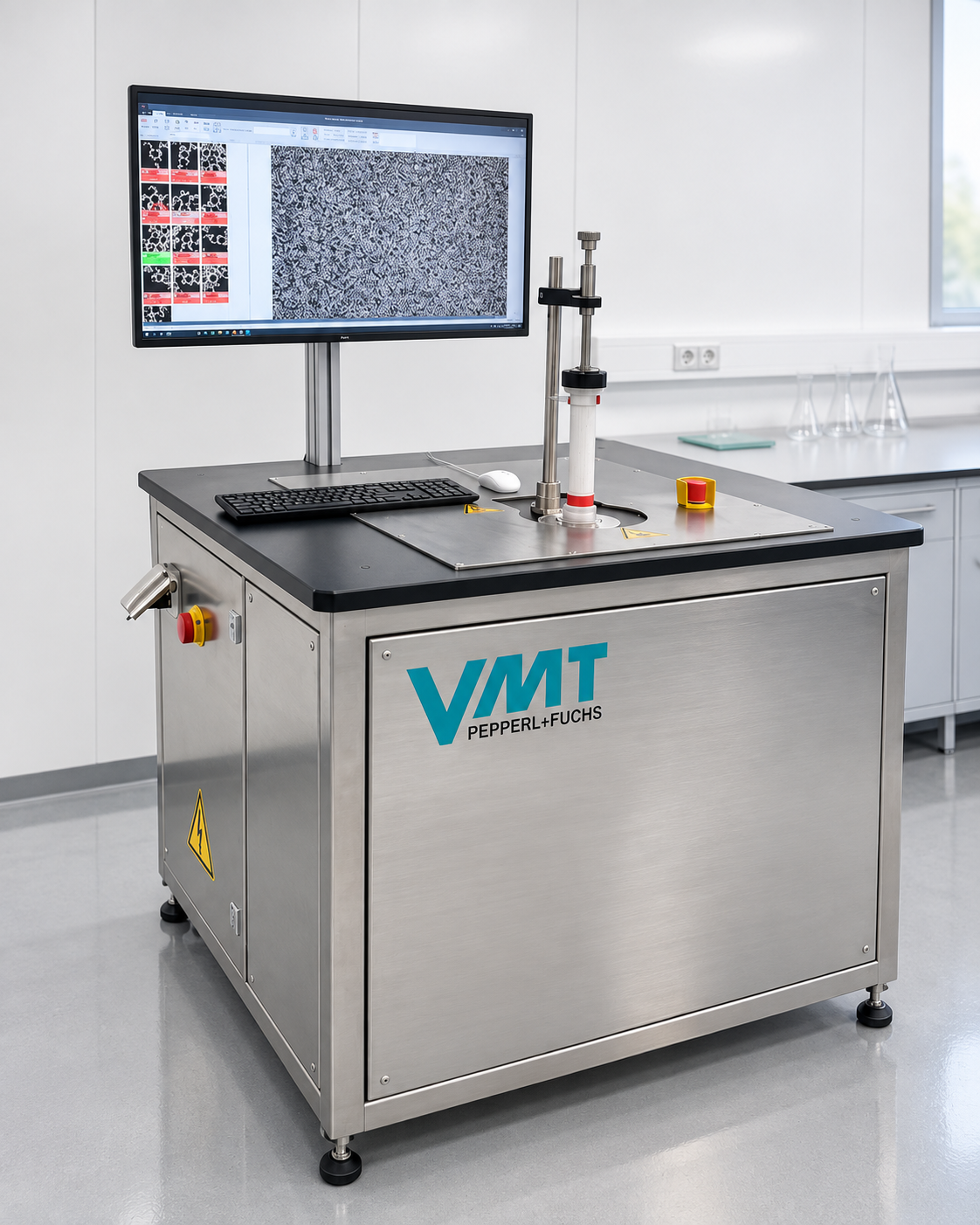
VMT FiberGeometryCheck is an image processing system designed for the automated measurement of fiber geometry during dialysis filter production. The system measures the wall thickness, roundness, and inner diameter of the hollow fibers, as well as fiber deformations, and assesses the geometry of the filter end. Measurement data is documented for each test object and evaluated against predefined limits. The standard version operates inline within the production line, measuring filter end geometry in sync with the production cycle. An advanced configuration is available as a fully automated inspection station for the sampling and measurement of individual fibers; this features microscope optics mounted on an X-Y positioning unit that scans the sample and stitches individual images together to form a complete image. Both versions utilize the same system architecture and software core. VMT FiberGeometryCheck is currently in use in multiple serial production environments for dialysis filters.

Micrometer precision

Hollow fiber wall thickness, roundness, and inner diameter in a single pass

Reproducible

Measurement values ​​independent of the operator and manual visual inspection

Scaleable

From in-line measurement at the end of the filter line to a laboratory testing station for individual fibers.
How it works

Sample feeding and test plan selection
The dialyzer is transferred inline from the production line to the testing position. At the laboratory test station, the fiber sample is inserted and tensioned. The test plan defines the measurement tasks, target values, and tolerances for each product type. Changing the product type does not require mechanical retooling.
Image acquisition and measurement
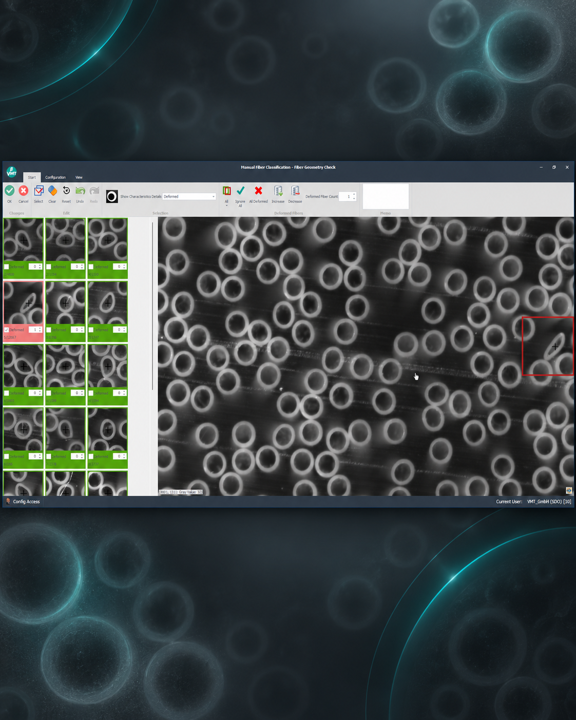
At the filter end, multiple camera stations capture the cut surface, supplemented by perspective views of the filter end's geometry. At the laboratory testing station, microscope optics scan the sample along the X and Y axes; the individual images are stitched together to form a high-resolution composite image. The wall thickness, roundness, and inner diameter of each captured fiber are analyzed, as well as any deformations in the fiber cross-sections.
Result and documentation
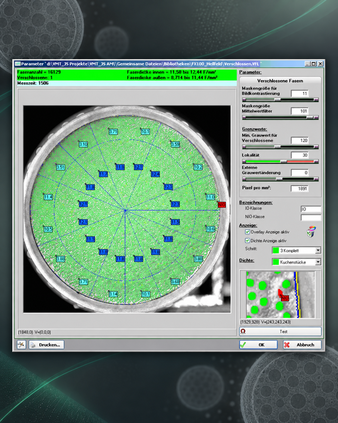
Each fiber is evaluated against established limit values, and the test object is classified as OK or NOK. Measurement values ​​are overlaid on the camera image and archived alongside it. In an inline setup, results are transmitted to the production line via the system controller, while at a laboratory test station, the output takes the form of a measurement report. This ensures the documentation is audit-ready without the need for manual post-processing.
01
How it works

Software & Usability

Operation
Operation is via the VMT-IS interface on the system computer. Inspection plan selection, the live image, and measurement results are all accessible on a single screen. Measurement values ​​and defect features are overlaid directly onto the camera image, with "not OK" (NOK) features highlighted in color. This allows the cause of an NOK result to be identified without the need for subsequent image review.
User Management and Documentation
Role-based user management with separate privileges for operation, setup, and administration. Changes to inspection plans and parameters are logged. Measurement data and associated images are archived and remain traceable for each inspected object. The audit trail and role-based privilege assignment support 21 CFR Part 11 requirements; the software core is designed for regulated medical device manufacturing in compliance with ISO 13485 and the MDR.
Configuration and parameterization
Measurement tasks are configured for each feature using target values ​​and tolerances, with pixel-to-millimeter conversion based on a calibration factor derived from measured sample parts. New product types are set up as additional inspection plans. Configuration and limit setting are performed without programming. Configurations and inspection plans can be saved and restored using a backup function. Outlook: In the future, VMT FiberGeometryCheck will run on VMT ONE—VMT’s new software platform—offering the same range of functions but with higher performance.
02
Software & Usability

Hardware

Camera and lighting
High-resolution monochrome area-scan cameras, designed to resolve individual fiber walls. Multiple camera stations operate in tandem at the filter end, two of which use perspective imaging to measure the filter-end geometry. The lighting is optimized to produce high-contrast images of the fiber edges. Automated camera self-tests for focus and illumination intensity monitor image quality during operation.
Optics and axis mechanics
A defining feature of this system configuration is the microscope optics mounted on an X-Y positioning unit. This setup enables resolution of the fiber wall while simultaneously covering the entire sample area through image field tiling. Acquisition points are stored as specific camera positions, with image capture taking place only once the axis has reached the target position. The testing station is designed as a fully enclosed automated system.
System platform and peripherals
VMT IPC industrial PC as the system platform; VMT IS software. Multi-camera systems operate as an integrated unit featuring centralized result analysis and a single interface to the system controller. Connection to the line is established via the production system's control interface. UPS, printer, and KVM switch available as options.
03
Hardware

Our team will be in touch as soon as possible.

FAST RESPONSE TIMES
EXPERT CONSULTING & SUPPORT
SOLUTION-DRIVEN APPROACH
01
02
03
04
Submit
Thank you! Your submission has been received!
Oops! Something went wrong while submitting the form.