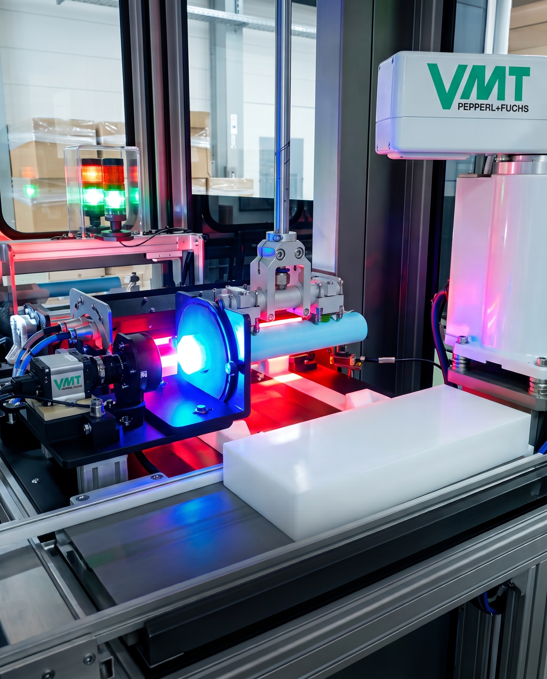
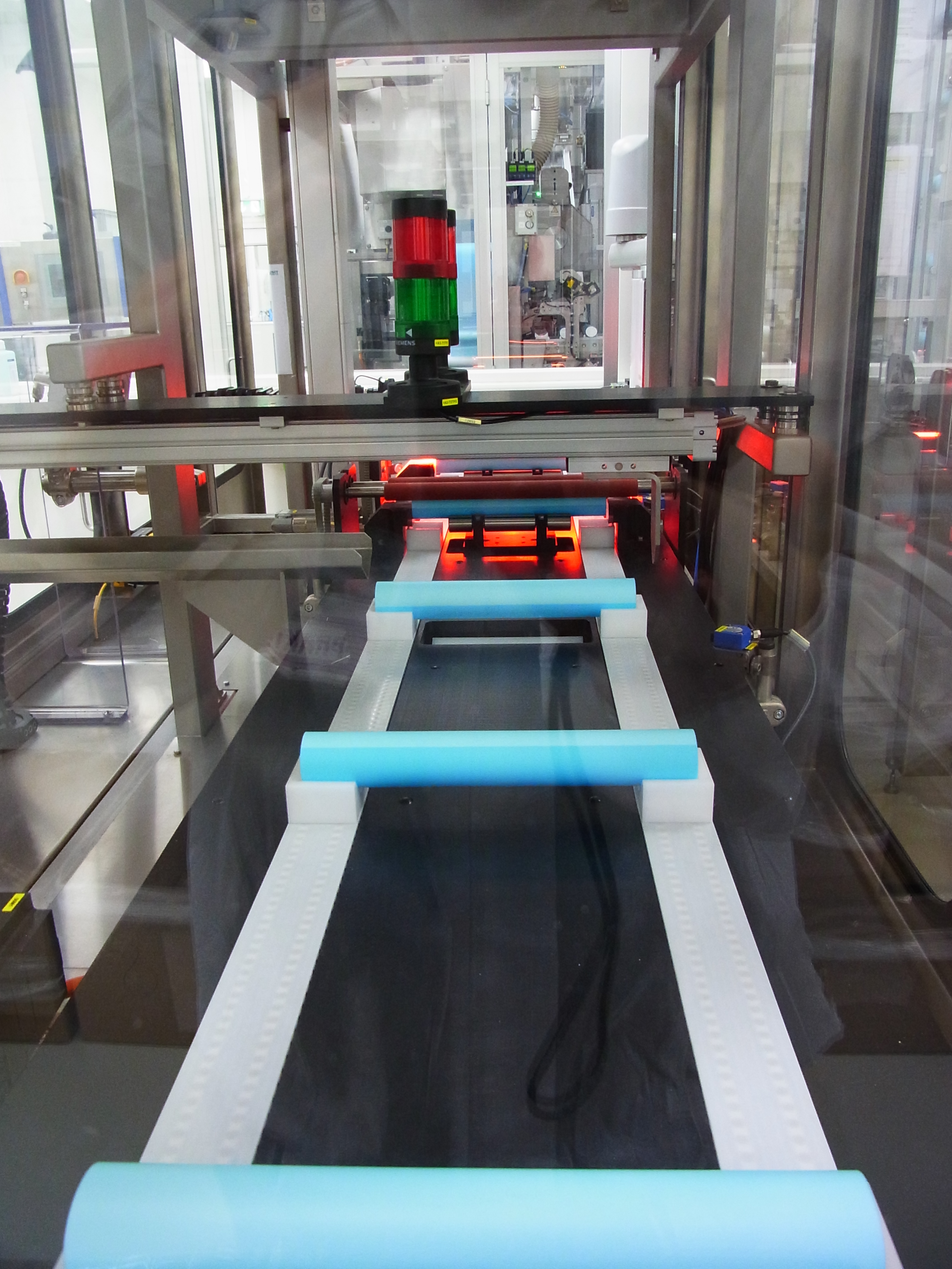
VMT FiberBundleCheck is an image processing system designed for the automatic inspection of wound membrane fiber bundles prior to their insertion into filter housings. The system captures the entire outer surface of the rotating bundle, detecting particles, fiber loops, misaligned fibers, dents, and protruding sections of the wrapping film. Defective bundles are rejected inline—preventing further value-added processing on units destined for scrap. Manual visual inspection of fiber bundles is slow, operator-dependent, and—in high-volume production—does not allow for comprehensive documentation. VMT FiberBundleCheck replaces this with an objective, reproducible inspection process that provides complete documentation of results. The system is available in two configurations: as a vision module for integration into existing bundling lines (connected via the system controller) or as a turnkey inspection station developed with our mechanical engineering partners, complete with handling and rotation mechanisms. The application has evolved over several generations of production systems and is currently in use worldwide in serial production.
Seamless
Rotating beam, overlapping inspection zones across the entire circumferential surface
Automatic type change
Inspection plan and camera parameters follow the system controller's type code.
Self-monitoring
Focus and illumination check of the camera system during every inspection cycle
How it works
Bundle pickup and position detection
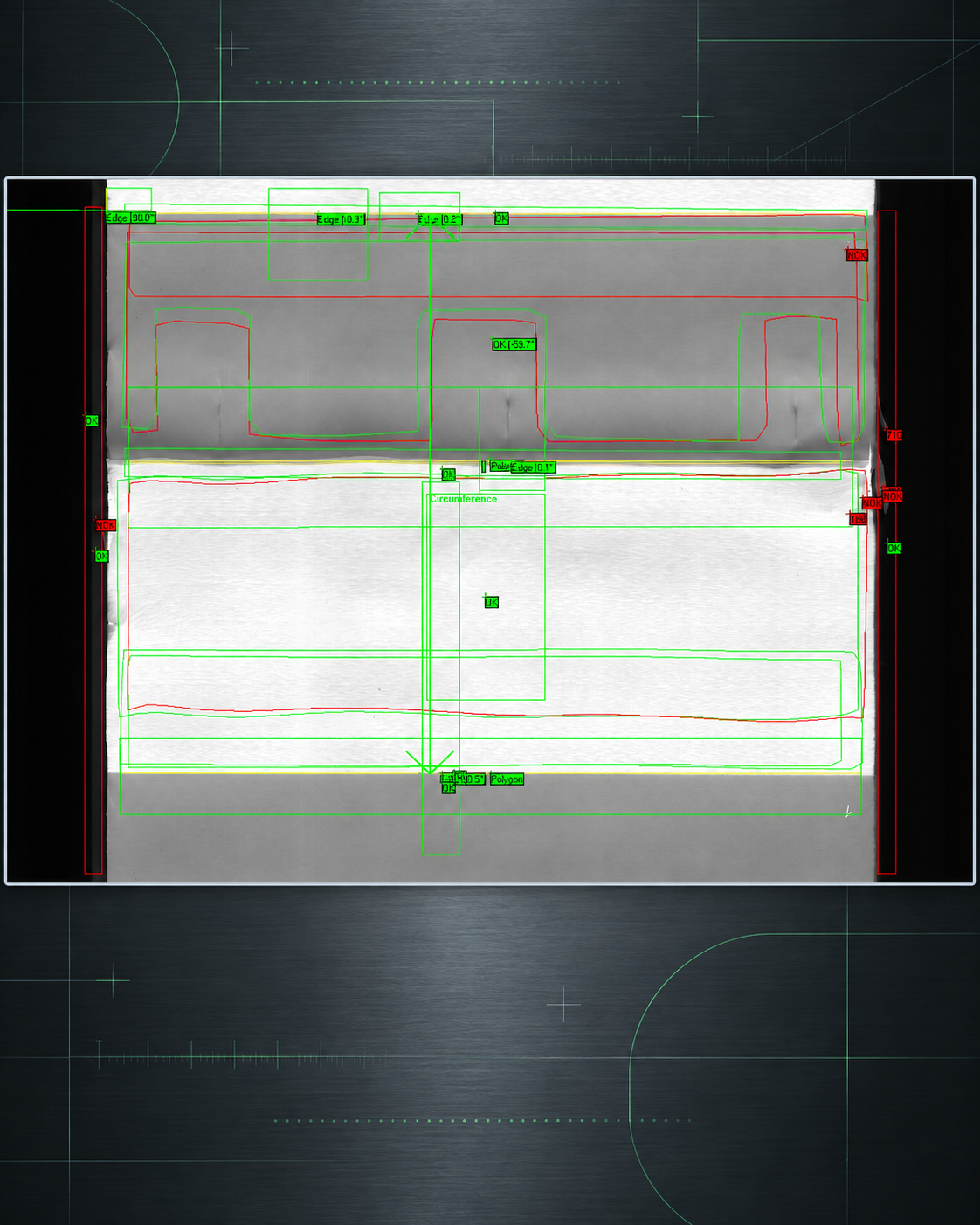
The system lifts the wrapped bundle from the transport line and sets it rotating at a constant surface speed. The control system transmits the type code and a start signal to the vision system. The bundle's position within the rotating fixture varies from one bundle to the next. A multi-stage position detection process scans the left edge of the bundle as well as the inner and outer edges of the film; polynomial approximation precisely aligns the inspection zones with the curved contour of the bundle. Consequently, all subsequent inspection tasks operate independently of the initial loading position.
Inspection process at two camera stations
Images are captured using line-scan cameras during rotation, allowing the lateral surface to be rendered as a continuous image. Two stations with different lighting geometries cover two physically distinct defect classes: the Red Station uses diffuse incident light with a steep angle of incidence to detect defects distinguished by brightness and contrast—such as dark particles in single- and double-layer film areas, bright fiber loops between film layers and at the inner film edge, foreign textile matter, protruding fibers or film, and faulty film cuts in the overlap zone. The White Station uses incident light directed at a shallow angle from one side to detect raised features: misaligned fibers beneath the single film layer, dents in the film, and weld spots. The inspection zones for the single-film section overlap to ensure no uninspected areas remain between them. Additionally, the bundle circumference is measured and evaluated against the specifications for the specific type.
Result, self-monitoring, and documentation
Once image acquisition is complete, the system evaluates the data and reports an overall result to the machine controller: good, not good, circumference out of tolerance, or a system self-test error. The controller rejects non-compliant bundles. During every inspection cycle, the camera system performs a self-check of image sharpness and illumination brightness, adjusting the exposure time for the next image accordingly. Error evaluation is buffered: while individual anomalies result in the rejection of the affected bundle, only multiple consecutive deviations trigger a system alert. This allows drifting optics to be detected before they lead to product slippage, without false errors stopping the production line. Results, statistics, and inspection images are logged at the station and are available for batch documentation.
01
How it works
Software & Usability
Operation
The system is based on the VMT IS image processing software. Upon startup, the software automatically begins operating in automatic mode at both stations; no manual intervention is required during series production. The interface displays the camera image with an overlaid result, the active inspection plan, measurement results, pass/fail statistics, and a real-time log of recent measurements. Both stations are accessed via a shared control unit.
User Management and Documentation
Parameter changes are only possible after logging in with a username and password; the user is automatically logged out when automatic operation begins. The audit trail is an integral part of the VMT software core: interventions and parameter changes are recorded in a traceable manner. The system thus supports cGMP and 21 CFR Part 11 requirements for electronic documentation; the specific scope is determined on a project-specific basis. Test results and statistics are continuously logged, and statistics are reset upon a product type change. A backup function is available to save the system configuration, offering both full backups and parameter-specific backups; each backup is uniquely identified by project, station, and timestamp and can be fully restored.
Configuration and parameterization
Each bundle type has a dedicated inspection plan with a corresponding set of camera parameters. Selection is based on the type code from the system controller; an invalid type specification triggers a feedback signal. Inspection tasks are configured using image filters and evaluation thresholds—involving image preprocessing for feature extraction, followed by assessment based on minimum size, contour, and angular properties. Inspection sensitivity can be tightened or relaxed via a single threshold value, without the need for programming. Dependencies between inspection tasks are visually indicated by color in the management interface, and inspection zones are locked to prevent accidental displacement.
02
Software & Usability
Hardware
Camera and lighting
Each station has a high-resolution line scan camera with a fixed focal length lens and external trigger, connected via Gigabit Ethernet. Red station works with two red line lighting as diffuse incident light, white station with a directed white LED spot as grazing light. Camera and lighting are firmly adjusted; The alignment is done once using an adjustment cylinder and remains unchanged across all bundle types.
Rotational handling and image acquisition
The bundle is lifted into a rotating mount and spun at a constant surface speed. A line-scan camera captures images based on a trigger signal over a defined number of lines, thereby recording the entire circumferential surface. A clipping algorithm identifies the characteristic light-to-dark transitions at the inner edge and tab of the film within the raw image and automatically crops the image to the relevant area. Exposure time settings are calculated based on the uncropped image and applied to the subsequent capture.
System platform and peripherals
Two camera stations, each with an industrial PC housed in a VMT control cabinet. Connection to the system controller is established via 24 V digital inputs/outputs on an industrial I/O card; signals transmitted include the start signal, camera trigger, type code, operating mode, individual results, and a watchdog signal. Both stations share a monitor, keyboard, and mouse via a switch. Power supply: 230 VAC.
03
Hardware
Our team will be in touch as soon as possible.
FAST RESPONSE TIMES
EXPERT CONSULTING & SUPPORT
SOLUTION-DRIVEN APPROACH
Thank you! Your submission has been received!
Oops! Something went wrong while submitting the form.