Special Solutions

Solving problems for which there are no solutions yet
Home
Life Science
Special Solutions
No Standard. Still Solved.
Five projects, five problems with no catalog answer.
Not every inspection task can be covered by a catalog system. Some components are too small, too transparent, or too varied in their forms, or they can only be measured after undergoing mechanical processing. In such cases, the solution is developed jointly with the customer, combining camera technology, lighting geometry, and analysis algorithms with—where necessary—handling and processing technology. The following projects demonstrate the scope of this approach. All the systems are currently in use in our customers' serial production or quality control operations.

One Process. Every Step Covered.

The right technology at every stage.
01

Foci-Quantification in the Immunofocus-Assay

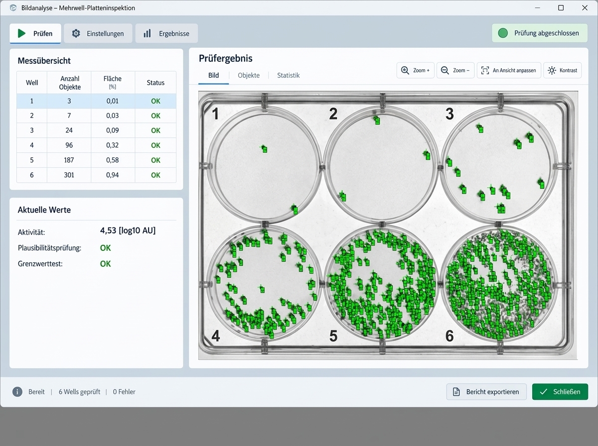
  • Scenario: The activity of serotype-specific foci is determined during vaccine quality control. Cell culture plates are manually loaded into a testing station, where they are imaged in a single pass.
  • Requirements: Reproducible counting results, independent of the day, time, or operator; unambiguous assignment of each result to the specific sample; and separate evaluation of the count and the condition of the cell monolayer.
  • Control tasks: Three images are captured per plate, each with appropriate lighting: one for reading the Data Matrix code, one for detecting defects in the cell monolayer, and one for analyzing the wells. Foci are counted, and the cell monolayer is evaluated using blob analysis. An incorrect count would directly affect the determination of the active ingredient's activity.
  • Special feature: Foci detection is performed using a neural network trained on labeled images. Each detected object is assigned a quality score indicating the detection confidence level; this allows for the suppression of false detections caused by image noise. All detected foci are marked in the image file, ensuring the count remains visually verifiable. Two self-checks safeguard the system: a control plate with defined characteristics must pass inspection at both the start and end of the daily shift, and stored reference measurements are re-evaluated using current parameters upon every login. If results deviate, the system does not authorize sample measurement. Subsequent visual verification must be performed by a user other than the one who measured the plates. User management and password policies are configured in accordance with 21 CFR Part 11 requirements.
02

Inspection of DNA- und RNA-Screentapes

  • Scenario: Screen tapes for DNA and RNA analysis undergo multiple processing stages during serial production. Three different components are inspected: the final tape, the carrier layer, and the screen tape.
  • Requirements: Detecting defect types with widely varying optical characteristics on the same component; inspecting all parallel lanes of a tape in sync with the production line; and ensuring traceable assignment of every image to the specific component.
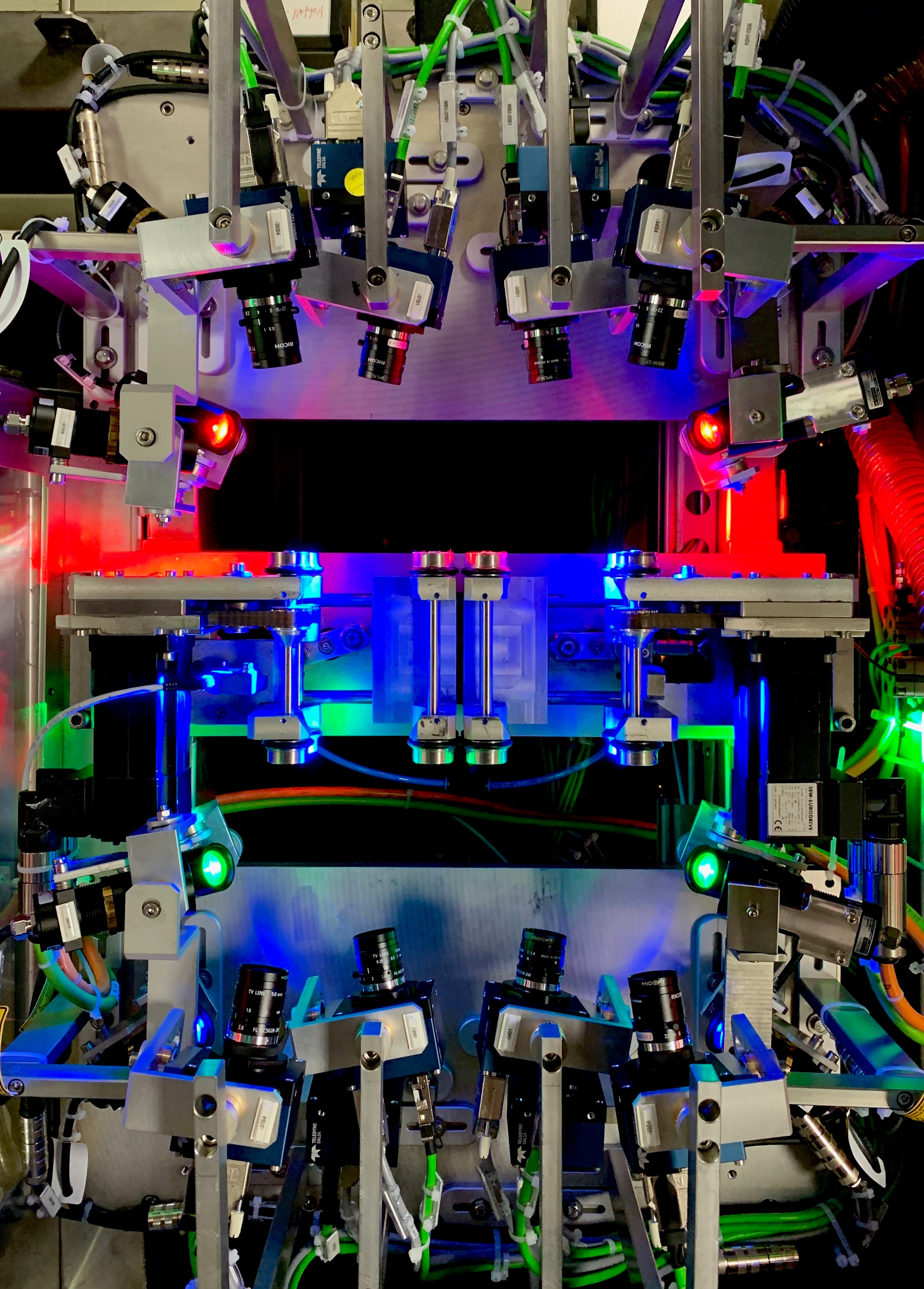
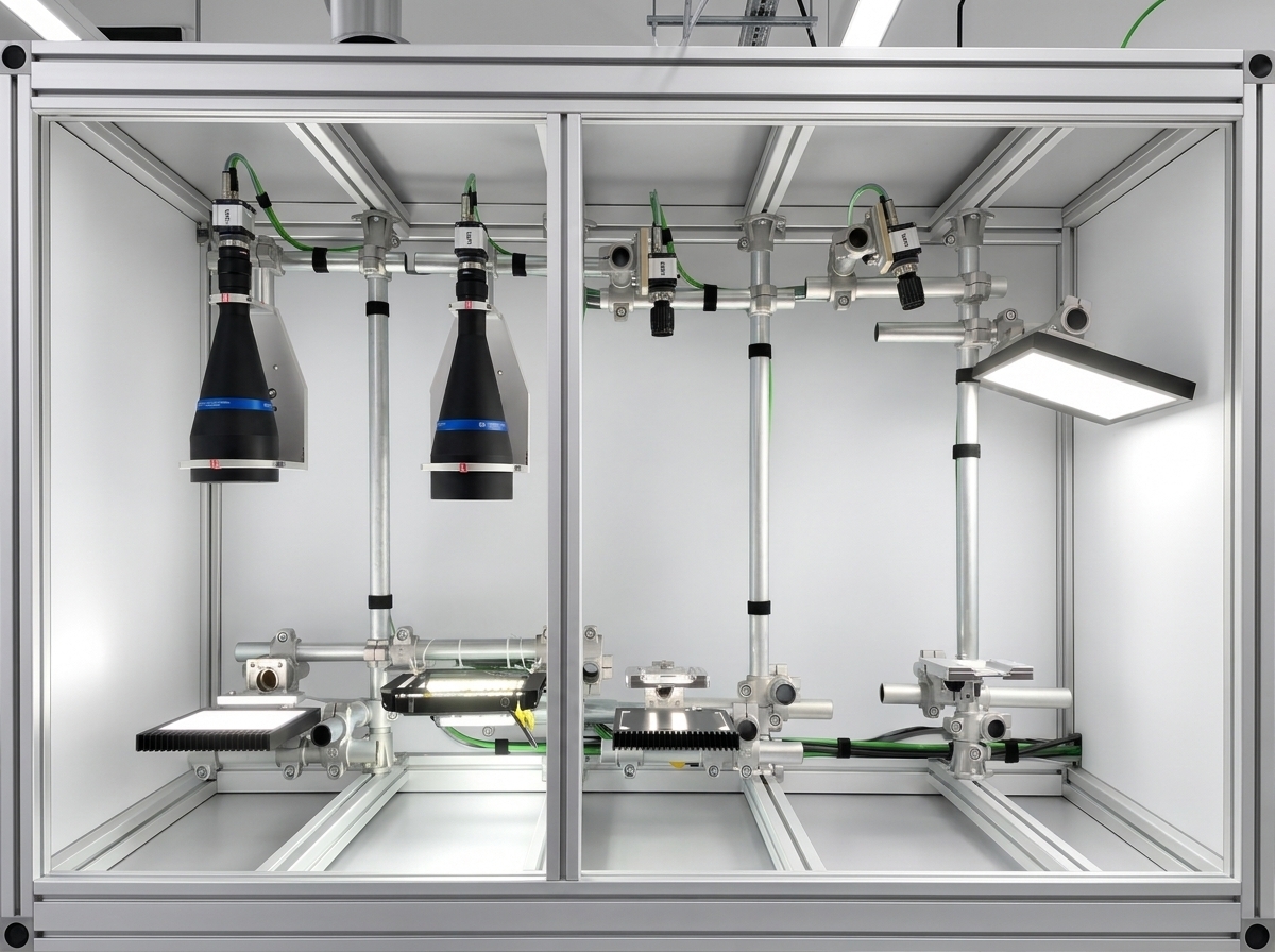
  • Control tasks: Detection of contamination, scratches, and fill levels. Eight camera stations utilize four different lighting geometries: darkfield, reflection, transmitted light, and transmitted light with a defined mask. An undetected defect would result in an erroneous analysis outcome for the end user.
  • Special features: Two aspects made this project exceptional. First, inspection parameters are set for a single lane and automatically applied to all other lanes using multi-feature position detection, keeping setup effort manageable. Second, the system includes a dedicated rework station. It does not have a camera of its own but instead loads images from all inspection stations via the network. The operator scans the rework magazine, views the images of the component in question, and makes a pass/fail decision. This allows false defects to be filtered out without compromising traceability. Additionally, each station checks its own lighting during every measurement; diminishing or failed lighting triggers an alert requiring acknowledgment rather than resulting in a silent rejection.
03

Seal seam inspection for rigid blisters

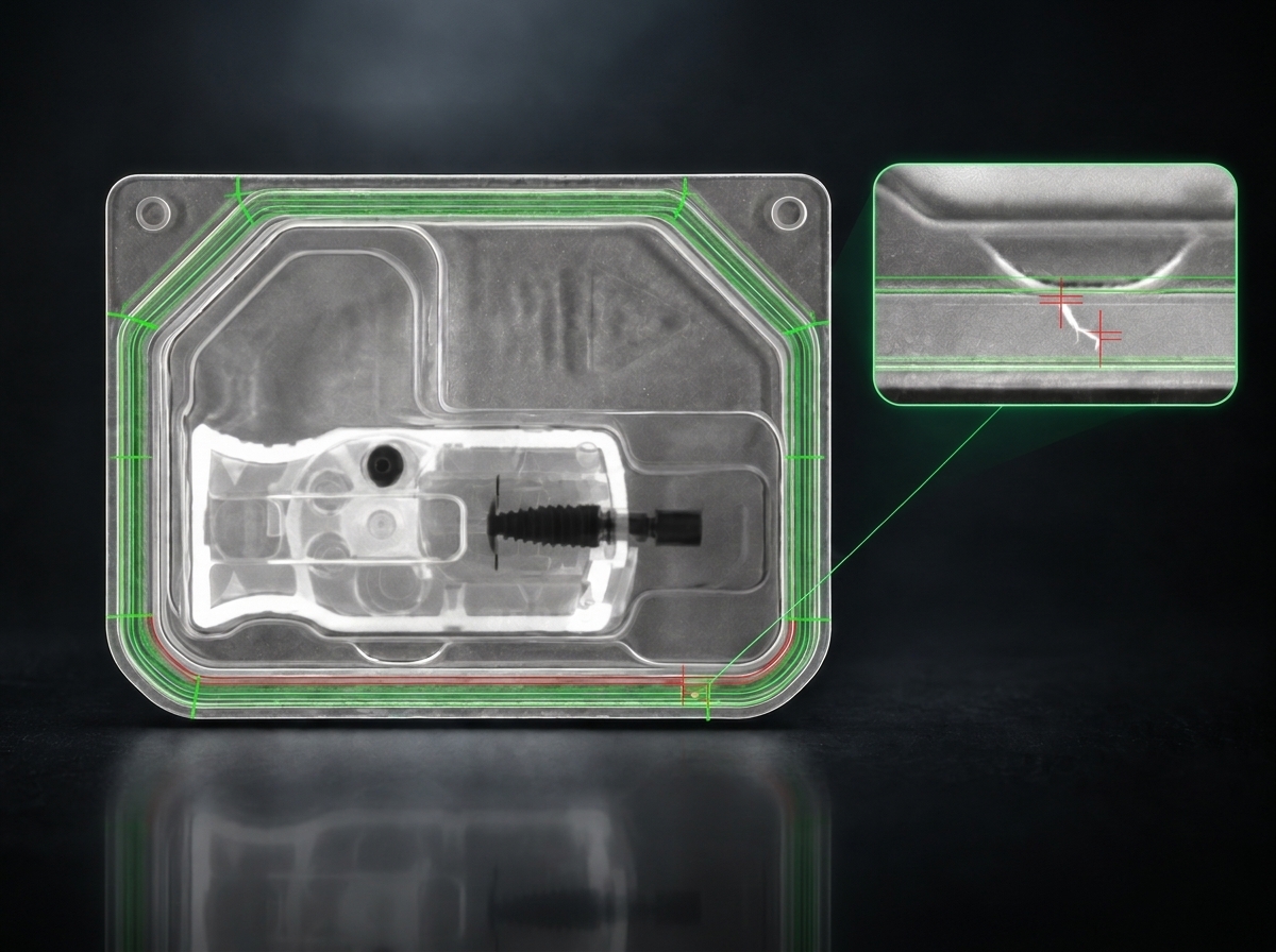
  • Scenario: Deep-drawn rigid blisters undergo sealing, printing, labeling, and die-cutting. The inspection system is integrated inline within the existing printing and labeling line, evaluating each blister in real-time during the production cycle.
  • Requirements: Evaluation of the seal seam along its entire perimeter, including corner radii; compensation for positional and die-cutting variations between blisters; and detection of very small, low-contrast defects within the sealing area.
  • Inspection tasks: Monitoring seal seam width across circumferential segments, as well as detecting particles in the sealing area, unsealed channels, and hairs. Unsealed areas appear brighter than sealed ones; an image filter highlights even subtle differences in brightness. Blisters failing inspection are rejected via the existing ejection station. A compromised seal seam results in a loss of the sterile barrier.
  • Special feature: The inspection sequence is structured in two stages. First, an upstream measurement task determines whether a blister is actually present in the inspection position. Only then does the actual inspection commence, ensuring accurate statistical data. Positional variations are compensated for using the area centroid and rotation angle, while rounded corners are additionally handled via a fitted polynomial. For hair detection, the image undergoes edge filtering followed by morphological dilation and erosion to close any contour gaps. Two light sources with different spectra, combined with a bandpass filter on the lens, ensure reliable differentiation between the sealing area and defects. All user access is logged via an audit trail.
04

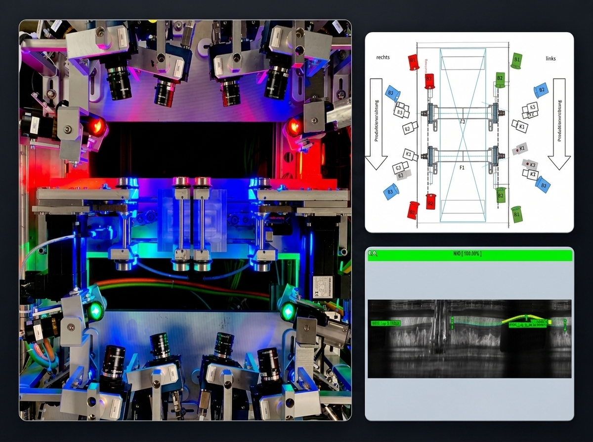
Control of detachment and particles at the dialyzer flange

  • Scenario: In the flange area of ​​a dialyzer, the filter housing is sealed with a screw cap. The filter rotates in front of the inspection system while three line-scan cameras capture the head section on each side of the filter.
  • Requirements: Inspection through either colored or transparent screw caps. Detection of separations from both the dialysis side and the blood side. Ability to inspect all filter sizes and membrane types without mechanical reconfiguration.
  • Control tasks: Detection of separations in the area where the housing and flange are screwed together, as well as trapped particles in the flange zone. Interfering features such as threads and injection points must not be classified as defects. Undetected separation compromises the dialyzer's seal integrity during operation.
  • Special feature: Six line-scan cameras per filter operate simultaneously on the same component area. To prevent the channels from interfering with one another, they are spectrally separated: each camera is illuminated with a specific color and equipped with a matching bandpass filter, ensuring that each channel sees only its own light. The image is generated through the component's rotation rather than a single snapshot. Camera parameters are automatically adjusted based on the cap color.
Back

Our team will be in touch as soon as possible.

FAST RESPONSE TIMES
EXPERT CONSULTING & SUPPORT
SOLUTION-DRIVEN APPROACH
01
02
03
04
Submit
Thank you! Your submission has been received!
Oops! Something went wrong while submitting the form.